Relay are everywhere, almost everywhere. That’s why we have to understand how to make relay driver so we can play it.
What is a Relay?
Relay is mechanical switch, just like switch in our home that we used everyday to switch the lamp. The lamp will on or off when we press on it. Inside the switch, it just mehanical part that can connect or disconnect the conductor when we press. Like switch that works in DC or AC. Relay just do the same things.
Why relay need driver?
We can’t use relay directly to microcontroller such as arduino or microprocessor like raspberry pi. This is because sometimes electronics device need more voltage or current to operate than arduino pin output can supply. So we need driver, if you want to understand more why we need driver, you can read here.
Relay Driver Example
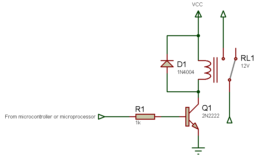
Now, we will make driver that can control a relay with various voltage. Here’s the schematic :

Parts needed is :
1 K resistor, NPN transistor (2N2222 or 2N3904 or other replacement), 1 diode (1N4004 or 1N4007 or other replacement).
The VCC needed is according to relay voltage. If you use 5V relay then you need 5V, if 12V then apply 12V and so on. And don’t forget to connect your relay power supply ground with microcontroller or microporcessor ground. If not, your driver will not working.
If you’re new to electronics and still confuse to read the schematic above. I will give you an hardware picture example on breadboard using arduino.

In picture above I give example of relay that using 9V VCC from battery to switch an red LED. If arduino gives HIGH output at pin 4, relay will connect LED to 9V battery. And if the output from arduino goes LOW, it will disconnect the relay and LED will turn off. You can use another load for relay like AC lamp we use everyday in home. Almost everything you can switch with relay, but pay attention to relay maximum ratings. Like maximum voltage and current. If you use relay above maximum rating, you can destroy the relay.
Here’s the example arduino sketch to blink the LED or other load using relay :
// the setup function runs once when you press reset or power the board
void setup() {
  // initialize digital pin LED_BUILTIN as an output.
  pinMode(4, OUTPUT);
}

// the loop function runs over and over again forever
void loop() {
  digitalWrite(4, HIGH);   // turn the LED on (HIGH is the voltage level)
  delay(1000);                       // wait for a second
  digitalWrite(4, LOW);    // turn the LED off by making the voltage LOW
  delay(1000);                       // wait for a second
}


