Introducing to L293D motor driver
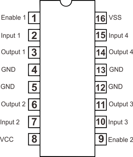
If you want to control an DC motor that can run forward or reverse you can do that in many ways. But I want to tell you the simplest way to drive DC motor. In this project we will control the DC motor using single IC called L293D. This IC is powerful enough to control DC motor with low current. Before we start the wiring. We will introduce you to L293D IC first. This is the pinout :

L293D can drive up to 2 motors with single IC. Use input 1 and Input 2 to control first motor. So first motor should be connected to Output 1 and Output 2. And if you want to use second motor, connect input control to Input 3 and Input 4. And motor to Output 3 and Output 4. VCC should be connected to 5V to power up the IC. VSS is input power for motors. So if you want to use 12V motor, this pin should connect to 12V power supply. Connect 12V and 5V ground to gnd, wire all gnd. And Enable pin is used to control speed of motors using PWM. Enable 1 used to control speed of first motor, and Enable 2 for second motor.
L293D schematic with motor example
So how we use this IC? check our example schematic below :

To Control first motor (left), you can give input from microncontroller like arduino to make motor run forward or reverse. Give Pin 2 HIGH/5V and Pin 3 LOW/0V to run motor forward. If you want to run motor reverse then give Pin 2 LOW/0V and Pin 3 HIGH/5V. Give Pin 1 (Enable 1) PWM input to control the speed. If you use arduino UNO you can give PWM from 0-255. Mean that 255 is full speed and 0 is stopped. And if you don’t want to control the speed you can just connect Pin 1 to 5V.
Control the second motor (right) use pin 10 and 15 to give the direction, and Pin 9 to vary the speed.
Example in bread board
Here’s example of using L293D with an arduino UNO and a DC motor

L293D single motor bread board
In picture above, motor power supply using a 4x AAA batteries. And 5V supply for IC given from arduino 5V.
Code example :
const int motorPin1  = 2;  // Pin 14 of L293
const int motorPin2  = 3;  // Pin 10 of L293

void setup() {
  //Set pins as outputs
  pinMode(motorPin1, OUTPUT);
}


void loop() {
  //This code  will turn Motor forward for 2 sec.
  digitalWrite(motorPin1, HIGH);
  digitalWrite(motorPin2, LOW);
  delay(3000);
  //This code will turn Motor reverse for 2 sec.
  digitalWrite(motorPin1, LOW);
  digitalWrite(motorPin2, HIGH);
  delay(3000);
}
If you want to drive High current DC motor, you can visit here.


hi, just want to point out that your schematic seems wrong. the vss should be the logiv voltage: 5v and the vcc can be 12v to power the motors. looks like it got swapped? or am I missing something here. I hope nobody gets it wrong.
hi, just want to point out that your schematic seems wrong. the pin 16(vss) should be the logic voltage: 5v and the pin 8(vcc) can be 12v to power the motors. looks like it got swapped? or am I missing something here. I hope nobody gets it wrong.