Introduction to SIM900A
SIM900A is a GSM module that function like phone. It can send a message, call a phone number and use GPRS to send data. Here’s the simple feature taken from it’s datasheet.
You can buy this device at link below (affiliate links) :
- Quad-Band 850/ 900/ 1800/ 1900 MHz
- Dual-Band 900/ 1900 MHz
- GPRS multi-slot class 10/8GPRS mobile station class B
- Compliant to GSM phase 2/2+Class 4 (2 W @850/ 900 MHz)
- Class 1 (1 W @ 1800/1900MHz)
- Control via AT commands (GSM 07.07 ,07.05 and SIMCOM enhanced AT Commands)
- Low power consumption: 1.5mA(sleep mode)
- Operation temperature: -40°C to +85 °C

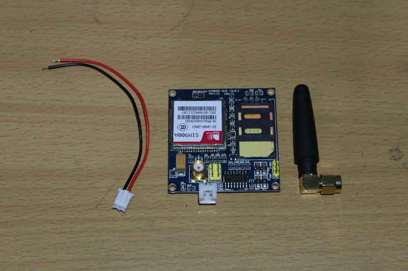
SIM900A comes in many module, many factory made product with connection module for easier to use by us. Because it will take many connection if we make circuit manually. In this tutorial, we will use SIM900A module like in picture below :
 SIM900A module package
Other type should be has same principle on how to use it. Usually just use different power consumption. Like voltage and current. This type can connected to 5V directly, which has provided by arduino. No need external power supply. Other type may need 9V or greater.
AT Command
SIM900A uses AT command to communicate and control the module. This means if you want to control SIM900A with arduino. The arduino should give an AT Command to control it. AT Command in SIM900A uses Serial port to communicate. As usual, serial needs two pins that is Transmitter (Tx) and a Receiver (Rx). AT command is a command that begin with “AT”.
AT Command sample :
AT+CMGF=1 //Sets the GSM Module in Text Mode
AT+CMGS //Send a message
Parts needed for this Tutorial
- SIM900A
- Arduino UNO
- SIM Card
- 4 male female jumper cable

We just need connect 4 wires to SIM900A module, that is power connection (VCC and GND). And Serial communication (RX-TX). Because we use arduino UNO which is use 5V operating voltage and has 5V logic level (TTL). So we need to connect arduino to 5RX and 5TX like in pinout picture below.

SIM900A and Arduino wiring connection
Wire SIM900A module to arduino UNO like this :
Arduino -> SIM900A
5V -> VCC
GND -> GND
10 -> TX
11 -> RX

Communication Test
If you already connect the module with arduino like in picture above, then this is the time to test communication between module and arduino, to make sure that arduino can give command to SIM900A module. Don’t forget to double check the wiring connection.
In this test, we will use AT Command to communicate with SIM900A module. If we send command “AT” the module should reply “OK”. And if that happen, this means the connection is succesfull. To do this, we need an arduino sketch like below :
#include <SoftwareSerial.h>
SoftwareSerial SIM900A(10,11); // RX | TX
// Connect the SIM900A TX to Arduino pin 10 RX.
// Connect the SIM900A RX to Arduino pin 11 TX.
char c = ' ';
void setup()
{
// start th serial communication with the host computer
Serial.begin(9600);
while(!Serial);
Serial.println("Arduino with SIM900A is ready");

// start communication with the SIM900A in 9600
SIM900A.begin(9600);
Serial.println("SIM900A started at 9600");
delay(1000);
Serial.println("Setup Complete! SIM900A is Ready!");
}

void loop()
{

// Keep reading from SIM800 and send to Arduino Serial Monitor
if (SIM900A.available())
{ c = SIM900A.read();
Serial.write(c);}

// Keep reading from Arduino Serial Monitor and send to SIM900A
if (Serial.available())
{ c = Serial.read();
SIM900A.write(c);
}

}
Upload the sketch above and open Serial Monitor. Don’t forget to use BOTH NL&CR in arduino Serial monitor option.
Test the connection by type “AT” and then enter. If the arduino reply “OK” means your connection is established and working. If still no answer from arduino then check your connection and wiring again.
Since we already success use an AT command to SIM900A module, now we can try another AT command. These are some basic AT command we can use :
Change mode to sms :
AT+CMGF=1
Read SMS in text mode :
AT+CNMI=2,2,0,0,0
Make a call :
ATD+1123456789; //replace with number and country code you like
Disconnect / hangup call :
ATH
Receive a phone call :
ATA
We will try an complete example how to send and receive message. Use the sketch below :
#include <SoftwareSerial.h>

SoftwareSerial SIM900A(10,11);

void setup()
{
  SIM900A.begin(9600);   // Setting the baud rate of GSM Module
  Serial.begin(9600);    // Setting the baud rate of Serial Monitor (Arduino)
  Serial.println ("SIM900A Ready");
  delay(100);
  Serial.println ("Type s to send message or r to receive message");
}


void loop()
{
  if (Serial.available()>0)
   switch(Serial.read())
  {
    case 's':
      SendMessage();
      break;
    case 'r':
      RecieveMessage();
      break;
  }

 if (SIM900A.available()>0)
   Serial.write(SIM900A.read());
}


 void SendMessage()
{
  Serial.println ("Sending Message");
  SIM900A.println("AT+CMGF=1");    //Sets the GSM Module in Text Mode
  delay(1000);
  Serial.println ("Set SMS Number");
  SIM900A.println("AT+CMGS=\"+6281542787536\"\r"); //Mobile phone number to send message
  delay(1000);
  Serial.println ("Set SMS Content");
  SIM900A.println("Good morning, how are you doing?");// Messsage content
  delay(100);
  Serial.println ("Finish");
  SIM900A.println((char)26);// ASCII code of CTRL+Z
  delay(1000);
  Serial.println ("Message has been sent ->SMS Selesai dikirim");
}


 void RecieveMessage()
{
  Serial.println ("SIM900A Membaca SMS");
  delay (1000);
  SIM900A.println("AT+CNMI=2,2,0,0,0"); // AT Command to receive a live SMS
  delay(1000);
  Serial.write ("Unread Message done");
 }
You can edit the sketch and add the AT command you want to use.
You can find Complete video tutorial here :

hi sir
can you help me on my module the signal’s LED still blinking fast whatever the periode you wait!
i tried many power sources, a tried all the possible sim cards.
thanks in advance.
It does not send my predefined number please explain me
Is phone number to send the message is GSM phone number?
Hi there I have tried everything as told but by sending AT it gives question mark this “?” not an “OK” I have checked wiring many times kindly tell the solution
Try using 9600 baudrate
Salut sa m’envoie point d’interrogation toujour
Did you find the solution? I am facing the same problem
hi sir whether 3g or 4g sim card , we can use
Hello Sir,
Can you recommend a good consultant to help development needs?
Best regards,
what kind of consultant did you need?
bro it was showing the sms sent and at last it was showing ERROR???? like this pls help me out of this
Hi, I think your instruction is wrong at
10 -> TX
11 -> RX
In the very bottom of arduino uno, there is a sign showing 0 -> RX and 1 -> TX, so I have to change 10 -> RX and 11 -> TX to make the module work.
Since my knowledge about arduino thing is still poor, so I could be wrong.
Best regards.
Thanks, your tutorial really works for me. May God bless you.
bonsoir broth le commande dit oki au test1
mais le test2 ne réponds pas
Thank for the tutorial. Would it be possible to pay you to complete the sketch to use a servo. Basically i want to send command and once sim900 receives the command its trigger a servo to move x position, hold the position for 3 seconds, and return to its default position.
If you think you can help, please let me know.
This blog post provides a good starting point for beginners interested in using the SIM900A GSM module with an Arduino Uno. It clearly explains the basic communication method using AT commands and highlights the necessary components.